Electrical Floor Plan Symbols EdrawMax Templates
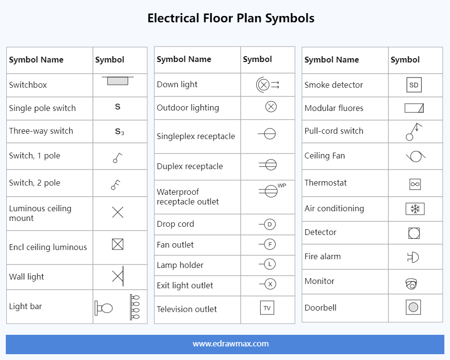
The basic symbol for most lights is a circle and, as with duplexes, variations on how it is drawn and abbreviations next to it convey additional and essential information. The key on the floor plans will explain the particular symbols used on any project.

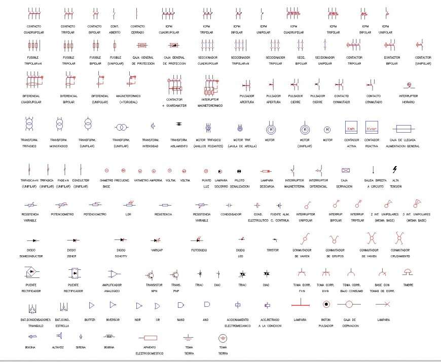
Electrical Symbols Free CAD Blocks And CAD Drawing
If you choose to sketch the electrical plans with paper and a pencil, it's recommended to study widely accepted electrical symbols to identify where wires, switches, relays, circuits, receptacles, and other individual electrical components are located in the home. This list of electrical drawing symbols is a great place to start. What You'll Need

Electrical Symbology Blueprint symbols, Electrical plan symbols
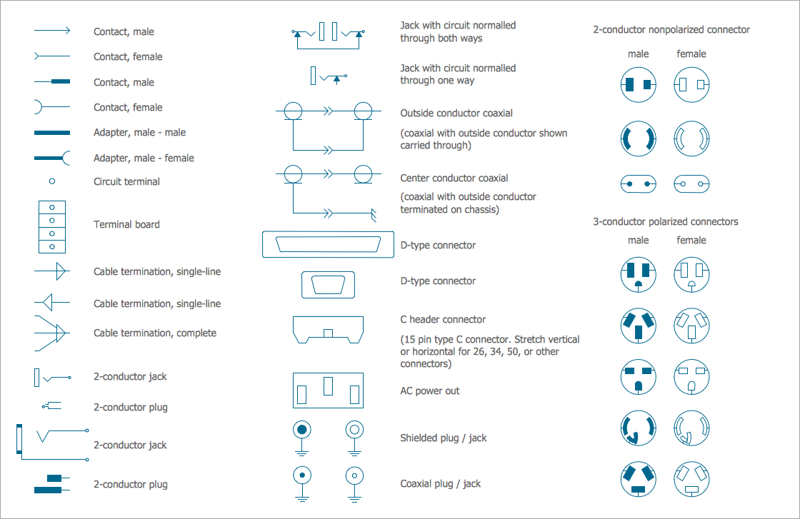
2. Outlets and Switches. Outlets and switches are the most common elements in an electrical plan. Electrical outlets, or sockets and other outlets are where you plug in appliances and electronic devices. Switches, conversely, control the flow of electricity to light fixtures. The electrical symbols used for these elements are standardized.

Comment comprendre les symboles des plans d'étage Studio Galerie
Basic electrical symbols contain earth electrode, cell, battery, resistor, etc. Whether you are a novice or a professional engineer, these basic symbols can help create accurate electrical and circuit diagrams in minutes. You can depict a complex electrical circuit with the standard and simplified electrical symbols.
Control Diagram Symbols Circuit Diagram Symbols Lucidchart These
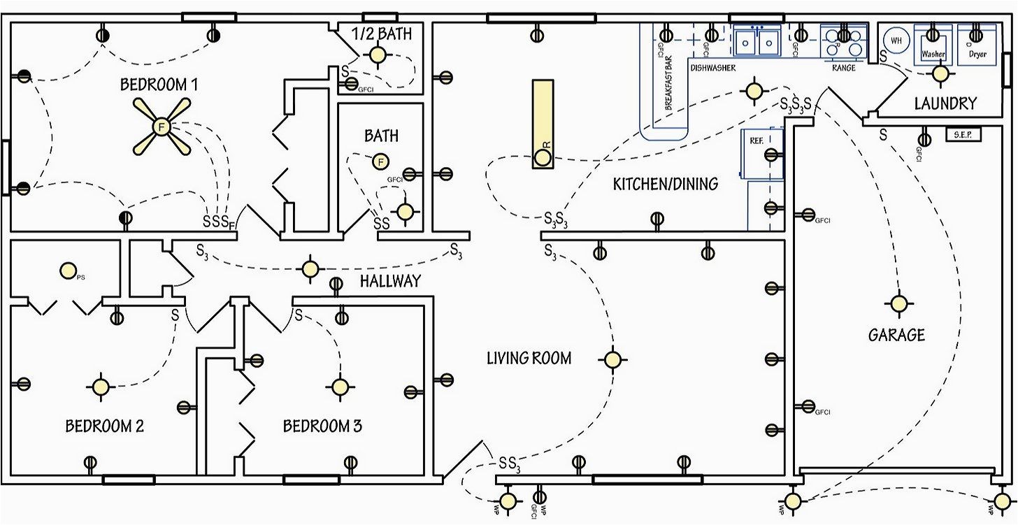
An electrical plan is a detailed drawing or diagram that shows the locations of all the circuits, lights, receptacles and other electrical components in a building. Professional electricians rely on electrical plans when installing or renovating electrical systems.
Free autocad electrical symbols sitfer
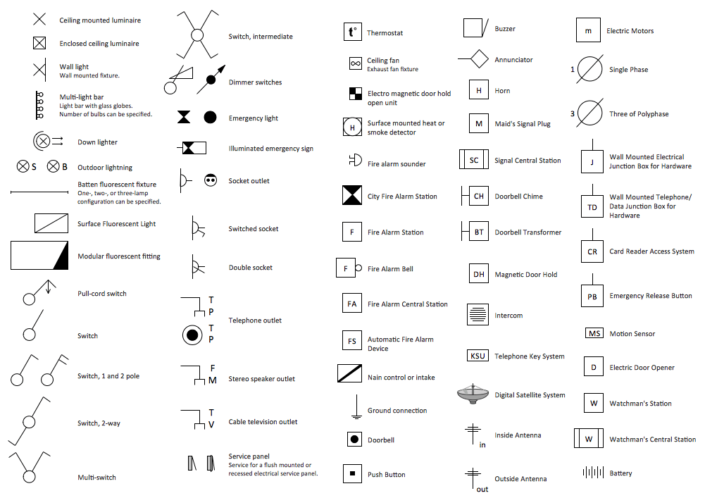
The most commonly used electrical blueprint symbols including plug outlets, switches, lights and other special symbols such as door bells and smoke detectors are shown in the figure below. Note: Explanations for common household electrical items such as three-way switches and switched duplex plug outlets are below the figure. Notes:
Electrical Symbols, Electrical Diagram Symbols
An electrical plan (sometimes called an electrical drawing or wiring diagram) is a detailed and scaled diagram that illustrates the layout and placement of electrical components, fixtures, outlets, switches, and wiring within a building or space.

Electrical Symbols General
Symbols used in an electrical plan are not always the same as those used in elevation or sec-tion drawings. Typically, symbols are graphics that may contain letters or numbers.. Electrical symbols and terms use a typical set of abbreviations next to the electrical symbols. They are used to represent and clarify specific switch types.

Important Ideas Building Plan Electrical Symbols, Amazing!
Electrical systems such as lights, switches, circuit breakers, distribution panels, and fixtures are denoted using various symbols described in legends. An electric planer is an instrument that helps to shave and shape wood. Legends contain abbreviations with symbols used for appliances, switches, panels, and other fixtures shown in a plan view.

Free CAD Blocks Electrical Symbols
Understand the symbols: Familiarize yourself with the symbols used in electrical plans. Common symbols include a circle for a light fixture, a square for an outlet, a triangle for a switch, lines representing wires, and more. Refer to a key or legend provided on the plan to interpret the symbols accurately.

Home Electrical Wiring Symbols
It is a type of technical drawing that delivers visual representation and describes circuits and electrical systems. It consists of electrical symbols and lines that showcase the engineer's electrical design to its clients. In short, an electrical plan describes the position of all the electrical apparatus.
How to Create House Electrical Plan Easily
Electrical Symbols Forward Building Plans For A House - Part 1. Forward examples, GFCI indicates a ground-fault circuit breaker (an outlet on a built-in fast acting circuit contact that prevents electric shocks and will typically be used with vents near water, in bathrooms and kitchens). The number 220 more to a duplex indicates it's a 220.
Electrical symbols Electrics Other
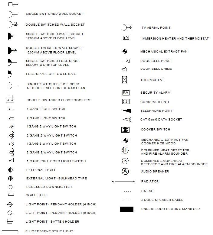
Electrical plan symbols are universally recognized icons or drawings used to depict the various components of an electrical system. These symbols are commonly used in architectural plans such as reflective ceiling plans to denote specific electrical devices, circuits, and connections. What is standard electrical symbols?

Common Electrical Symbols Electrical symbols, Blueprint symbols, Dc
An electrical plan is a visual electrical blueprint where all the electrical points of a building will be located. It describes the connection between the circuits, the number of switches and the location of their outlets, the position of lighting fixtures and any other electrical appliances.

electrical outlet symbol Floor plan symbols, Electrical symbols
Electrical symbols are used on home electrical wiring plans in order to show the location, control point (s), and type of electrical devices required at those locations. These symbols, which are drawn on top of the floor plan, show lighting outlets, receptacle outlets, special purpose outlets, fan outlets and switches.
Electric Wiring Symbols
All electrical symbols are only visible on 2D Floor Plans. They are part of our full product library, available for Pro and Team customers. This article explains how you can create your electrical floor plan with RoomSketcher. Just follow these four simple steps: Step 1: Draw your floor plan; Step 2: Add electrical symbols; Step 3: Add annotations
